
Wireless Charging Integration for Mobile Robots: How to Verify Energy Restored at the Dock
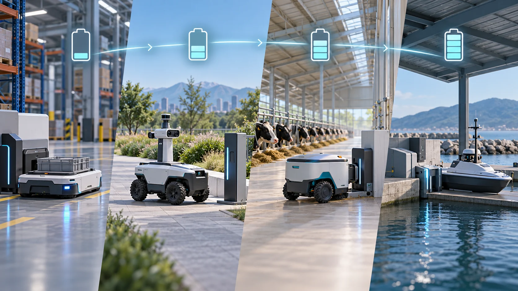
Concept illustration. The settings, charging stations and battery icons do not represent a specific product, delivered project or measured result.
An AGV or AMR arrives at a station, an inspection robot returns to its dock, or an unmanned surface vessel (USV) berths. Arrival establishes only that the vehicle reached its intended location. Even a “ready” indication on the charger does not show that the battery has recovered enough energy for the next mission. When battery charge falls over successive cycles, start with two questions: How much time was actually available for charging, and how much net energy entered the battery?
These questions apply across mobile-robot applications. This article explains how to use duty-cycle records, distinguish arrival from verified charging, and agree on acceptance evidence. Wireless power transfer is the focus, but the same energy accounting can also be used when comparing contact charging. It does not replace the design instructions for a particular battery, industry or charger.
How much of the day is actually available for charging?
Record a representative operating day. “The robot spends several hours at the dock” is not enough: separate each cycle into work, return travel, docking, preparation, actual charging and departure.
| Record | Question it answers |
|---|---|
| Start and end of each mission, plus return travel | How much energy does the mission consume, and what reserve is needed to reach the charging location? |
| Arrival and next departure | How long is the nominal docking window? |
| Alignment, mooring or securing, charge authorization, start-up and retries | How much of the window delivers no energy to the battery? |
| Battery-terminal voltage and current, or available energy records | How much net energy actually enters the battery? |
| Computing, communications, thermal management and other loads active while docked | Could the battery still be discharging while the charger supplies power? |
| Temperature, state of charge, current limits and fault states | Why does charging speed differ between stops? |
For an initial estimate of each stop:
Usable charging time = docking window − time without actual battery charging
Net energy restored ≈ average net battery charging power during that period × usable charging time
Use Wh for energy, W for power and h for time; convert minutes to hours first. The relevant power is what enters the battery. It is not AC input power, transmitter nameplate power or the charger’s displayed output. If the battery-branch voltage and current measurement already reflects the robot’s auxiliary loads, do not subtract those loads again. Battery condition and controller limits change charging power, so this average-power equation is a planning check; review the complete recorded interval before accepting a design.
Then examine successive operating days. Is usable battery energy falling at the end of each day? Before each mission, is there enough reserve to finish it and return? A daily energy balance alone does not prove that every individual mission is feasible. If system demand exceeds the power the charger actually supplies during a stop, the battery may still experience a net discharge. Use battery-side records to judge the result.
Arrival, permission and energy transfer are different states
For an integration discussion, record each of the following events separately. This is a proposed interface checklist, not a claim that all products use the same protocol:
Request recharge → arrive and confirm position → battery permits charging → charger ready → verify net battery charging → meet departure criteria → stop power transfer → resume work
If a stop restores no energy, the logs should show where the sequence stopped. The vehicle may have missed its target position; alignment may exceed the candidate charger’s specified limits; the battery may prohibit charging; the charger may fail to start; or the charger may be supplying power while the battery still has no net charge. An arrival lamp cannot substitute for battery-side evidence. The integration plan should also define when to stop, how many retries to allow and what fault to report.
The battery and charger must match on charging-voltage range, permitted current, charging strategy, temperature limits and fault response. If the battery pack has a battery management system (BMS), the controller must handle its permission or inhibition signals correctly. For systems without a BMS, follow the battery manufacturer’s charging-control and protection requirements.
A shared calculation does not mean a shared installation design
The energy questions are common, but docking conditions vary. These are design variables to investigate, not descriptions of completed projects.
| Application | Additional conditions to check |
|---|---|
| Factory AGV/AMR | Can the vehicle charge briefly between loading, unloading or queuing? Do floor space, traffic clearance and fleet scheduling permit the stop? |
| Indoor or outdoor inspection robot | What conditions allow the mission to resume, and how are unattended faults reported? Outdoors, also check rain, temperature and installation exposure. |
| Livestock mobile robot | Can debris, washdown procedures, cleaning chemicals or moving mechanisms affect the charging units and cables? |
| USV charging at a shore facility or surface berth | What movement remains after berthing, how is position maintained, and what are the moisture, salt-exposure and shore-power interface conditions? Underwater charging is a separate design problem and cannot be inferred from a shore-side solution. |
For a wireless option, check the candidate model’s specified transfer gap, lateral and angular misalignment, mounting space and thermal requirements. For contact charging, assess contact cleanliness, pressure, wear and protection. The better choice depends on site maintenance, docking performance, battery limits and system cost; neither “wireless” nor “automatic” settles it. Autonomous return, automatic docking, charge authorization and wireless power transfer are separate functions.
Where washdown, debris or moisture is present, assess the charging units, connectors, cables, brackets and control enclosure together. An ingress-protection rating on one component does not prove that the entire installation withstands a particular cleaning chemical or every washdown procedure. Check the site’s conditions against documentation for the candidate equipment and complete installation.
What would demonstrate a successful installation?
The following are proposed acceptance records, not completed tests. Verify abnormal conditions using methods approved by the relevant suppliers, without bypassing protection.
| Record | What it should demonstrate |
|---|---|
| Timeline across representative missions and repeated stops | Energy used on each mission, docking windows, delays without charging and actual charging time |
| Battery-side current, power or energy trend | Whether arrival produces net energy replenishment, and whether it supports the next mission and repeated operation |
| Normal stops and stops within specified alignment limits | Actual position, time to charging and number of exceptions |
| Charging inhibited, communication lost or alignment failed | Safe stop, limited retries and an intelligible fault report |
| Installation and maintenance check | Whether the specified environment, cleaning process, connections and service space match the candidate equipment documentation |
Before discussing a specific model, gather the mission timeline, battery chemistry and voltage range, allowable charging current, BMS interface or the battery manufacturer’s charging-control instructions, energy-use and docking records, plus mounting and environmental requirements. Without these inputs, the team can still define the state sequence and measurement plan, but cannot promise the required power, alignment tolerance, continuous operating time or final product choice.
For projects involving moisture, the waterproof wireless charging series offers an initial view of candidate products. You can contact UA37 with the project constraints. A catalogue heading does not replace model selection or field verification.